
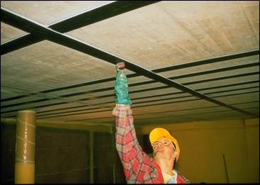
Strengthening by FRP
FRP Applications:
|
|
 |
 |
| Compression Strengthening | Shear Zone Strengthening | Shear Strengthening |
 |
 |
 |
| Flexibility increasing | Shear Strengthening | Flexural Strengthening & Deflection controlling |
 |
 |
 |
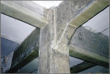
| Connection Strengthening | Shear & Flexural Strengthening | Shear & Flexural Strengthening |
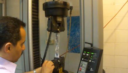
| FRP Tests | ||
 |
 |
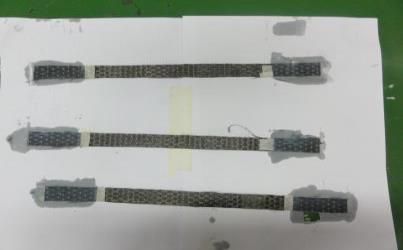 |
| Execution Test | Material Test | Material Test |
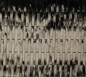
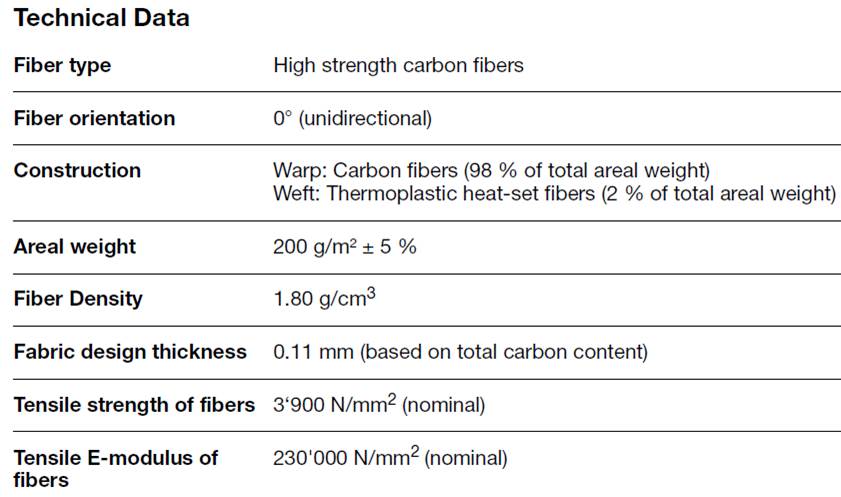
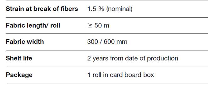
| Tensile comparison of FRP materials | ||
 |
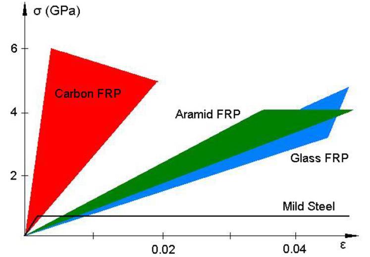 |
| Carbon FRP | |
 |
|
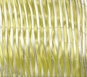
| Glass FRP | |
 |
|
| Aramid FRP |
FRP Designing
Reasons for strengthening
- Deterioration due to ageing
- Crashing of vehicles into bridge components
- Degradation such as corrosion of steel reinforcement
- Poor initial design such as corrosion of steel reinforcement
- Lack of maintenance
- Accidental events such as earthquakes
- Increase in service loads
- Change to the structural system
- Large crack widths
- Large deformation
Advantages of FRP as compared with steel
- Low weight and therefore easier application
- Very flexible during installation
- High strength ( although this strength cannot be exploited in unstressed applications )
- Good fatigue resistance
- Immunity to corrosion
Disadvantages
- Performance under elevated temperatures
- Effect of UV radiation
- Application of FRP and adhesives need qualified personnel
- Adhesives are dangerous for people and environment
- Material behavior: linear elastic to failure
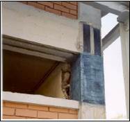
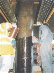
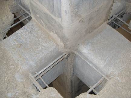
Column strengthening
Short Circular Columns in Pure Compression
Confinement:
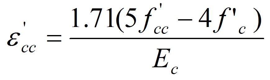
The compressive strength of the confined concrete, f’cc , is determined from the following equation:
![]()
For a continuous confinement, the volumetric ratio of the FRP strength to the concrete strength is defined as:
The ultimate confinement pressure due to FRP strengthening, ffrp , may be determined as:
According to Theriault and Neale (2000), the FRP confining wrap is required to develop a minimum confinement pressure:
![]()
To limit axial strains that may occur in a heavily strengthened column, the factored strength due to the concrete of an FRP confined column should not exceed the nominal strength of the concrete of an un-strengthened column
![]()
where ke is a strength reduction factor applied for unexpected eccentricities and, α1 , the ratio of average stress in the rectangular compression block to the specified concrete strength.
The factored axial load resistance, Prmax, for a confined column is given by the following equation:
![]()
Short Rectangular Columns in Pure Compression
Confinement:
the columns must have their corners rounded so that their radii, r , satisfy the lesser of the following conditions:
![]()
![]()
The compressive strength of the confined concrete is determined from the following equation:
![]()
For a continuous confinement, the volumetric strength ratio is defined as:

The confinement pressure due to the FRP strengthening of a rectangular section is computed as:

where the FRP strain, εfrp, is equal to 0.002 for non-prestressed confinement and Efrp is the modulus of elasticity of the FRP.
The effectiveness of the confinement pressure is far less for rectangular sections than it is for circular columns.
Columns Flexural Strengthening
 |
 |
 |
| Column flextural strengthening with end anchorage | ||
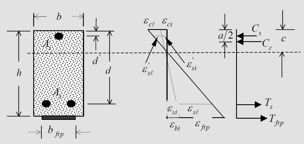
Forces and strains diagram:
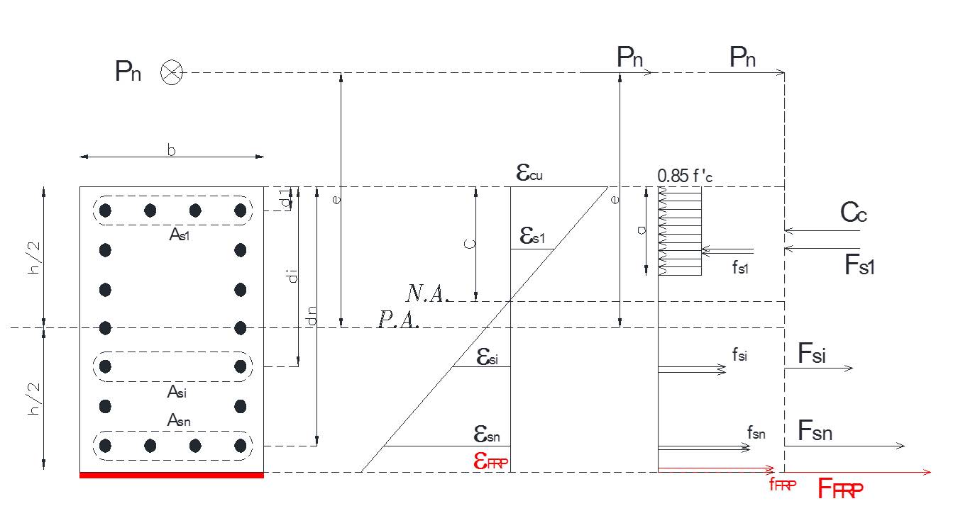
Determination of Flexural Capacity of Concrete Columns:
Step1. Guess the distance of Neutral Axis from the Compressive Axis and calculation
the height of equivalent rectangular stress block (a).
![]()
Step2. calculation of stress and force in rebar and calculation of concrete force.
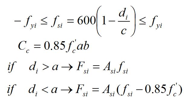
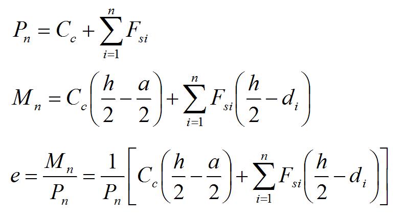
Step3. Pn and e will be calculated by the following equations:
Equilibrium Equations:
Step4. For each supposed C, will obtained unique Pn , Mn & e. By Try and Adjustment
Method, desired e will be obtained.
If obtained e in step 3 is equal to e0 (desirable e), e is acceptable; If e<e0 must
Select a smaller C and If e>e0 must select a bigger C.
The above steps 1 to 4 will use in calculation of Interaction Curve in Strengthened
Column by FRP, But Mn & e must calculated by following equations:
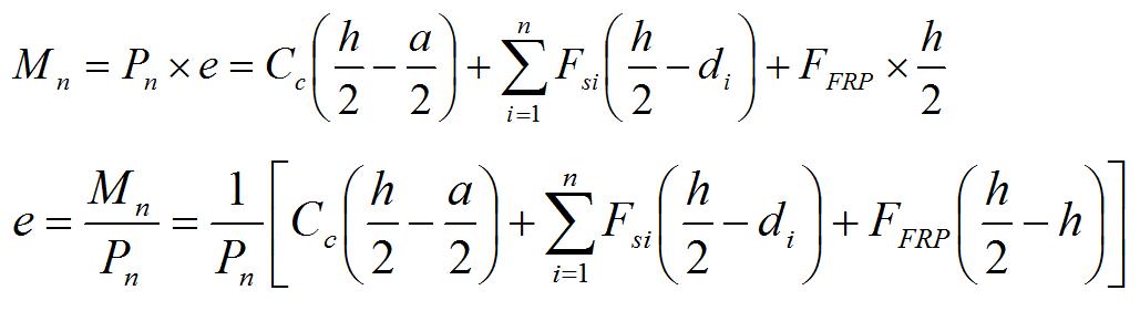
The above equations are based on ACI 318. If we use фc f’c instead of f’c and фy fy
Instead of fy , they will change into CSA code.
Ductility:
For seismic applications, FRP jackets should be designed to provide a confining
stress sufficient to develop concrete compression strains associated with the
displacement demands. The maximum usable compressive strain in concrete for
FRP-confined circular reinforced concrete members can be found by use of
following Equation (Mander et al. 1988).
While the confinement of rectangular columns have very low efficient for
increasing the axial strength, it could be very effective for improving the ductility
of rectangular columns and ductility increasing leads to the reduction of earthquake forces.
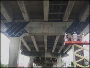
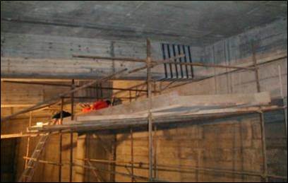
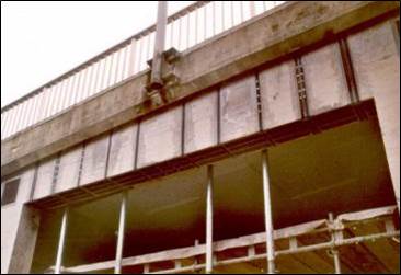
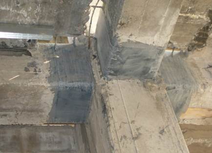
Beam strengthening
Flexural Failure Modes:
Four failure modes may occur for a beam strengthened with externally-bonded FRPs:
Concrete crushing;
Steel yielding followed by concrete crushing;
Steel yielding followed by FRP rupture;
Debonding of the FRP reinforcement near or at the concrete/FRP interface.
Forces and strains diagram:
 |
|
Stress and Strain Distribution (Tension and Compression Reinforcement) |

![]()
![]()
![]()
Mode 1: Compression failure of concrete
When neither the compressive nor tensile steel reinforcement have yielded, the position
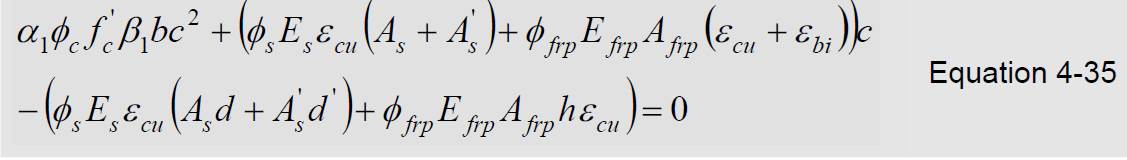
of the neutral axis is determined by a quadratic equation in terms of c in the form:
Check the strains in the materials to verify whether the assumed failure mode is correct:


The resisting moment is computed from:
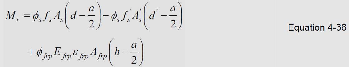
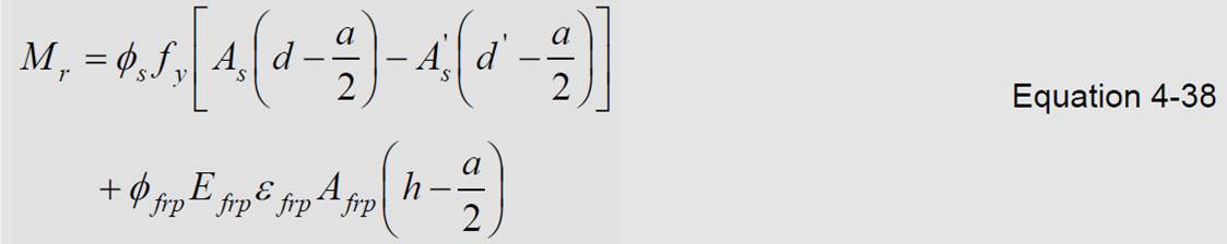
Mode 2: Steel yielding followed by concrete crushing
When both the tensile and compression steel have yielded, Equations 4-35 and 4-36 become:
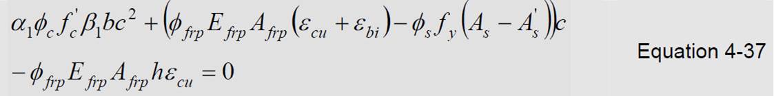
Check the strains in equations 4-34a, 4-34b and 4-34c by c obtained from equation 4-37:
In order to compute c when (ε’s ≥ εy ) & (εs ≤ εy ) or (ε’s ≤ εy ) & (εs ≥ εy ) one must use Equations 4-33 and 4-34a or 4-34b.
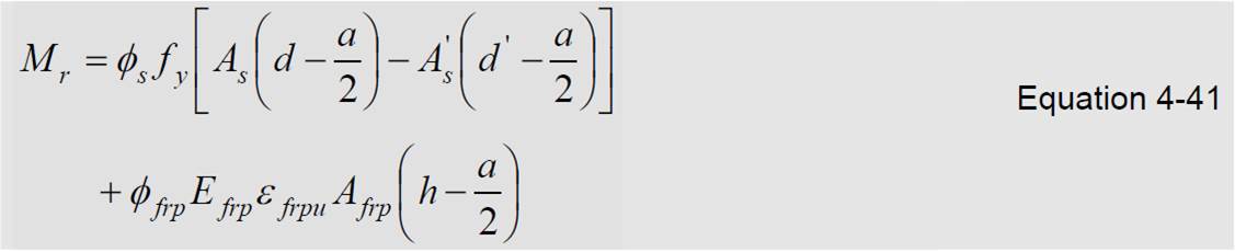
Mode 3: Tension failure of FRP
When the failure mode is FRP rupture in tension, the tension steel has invariably yielded (εs ≥ εy ) and the strains are computed as;


The position of the neutral axis is obtained by combining Equations 4-33 and 4-39a, and by replacing the strain in the FRP by the
ultimate tensile strain. After verifying for yielding of the tension steel using Equation 4-39b, the resisting moment is then computed as:
![]()
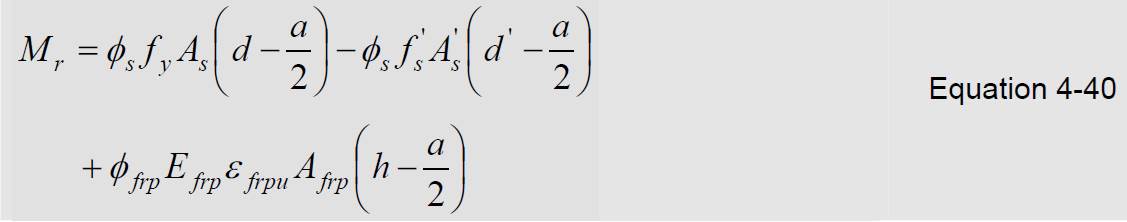
When both the tensile and compression steel have yielded, Equation 4-40 takes the form:
Shear Strengthening
 |
 |
 |
| Effectiveness will be decrease from left to right |
||
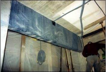
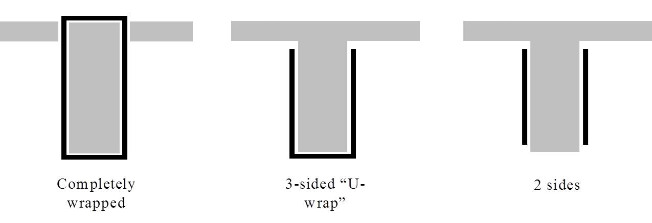
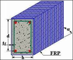
Fully Wrapped Configuration
 |
 |
 |
Completely wrapped
(Drill through slab) |
 |
Shear in Beam
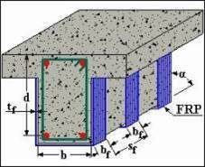
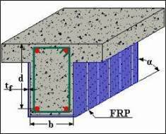
FRP materials may be applied as external stirrups to increase the shear strength of reinforced concrete sections. |
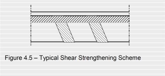 |
Design Principles
![]()
![]()
![]()
with Av and s the area and spacing of the transverse steel reinforcement, respectively. The contribution of the FRP is:
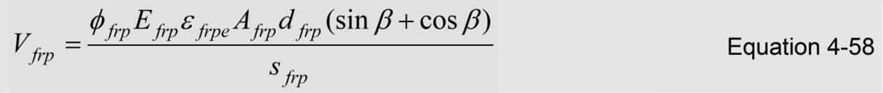
![]()
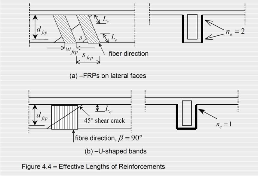
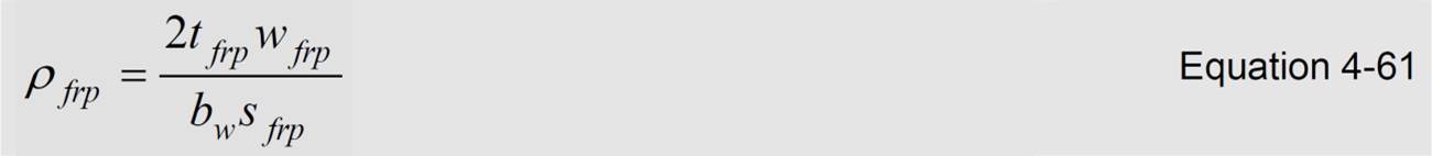
The effective depth of the FRP stirrups, dfrp , is measured from the free end underneath the slab to the bottom of the internal steel stirrups, or is equal to h when the section is totally wrapped.
The effective FRP strain ε frpe is found either by testing or by using Equations 4-60a and 4-62 below. The effective
strain ε frpe must however be limited to a value of 0.004.
![]()
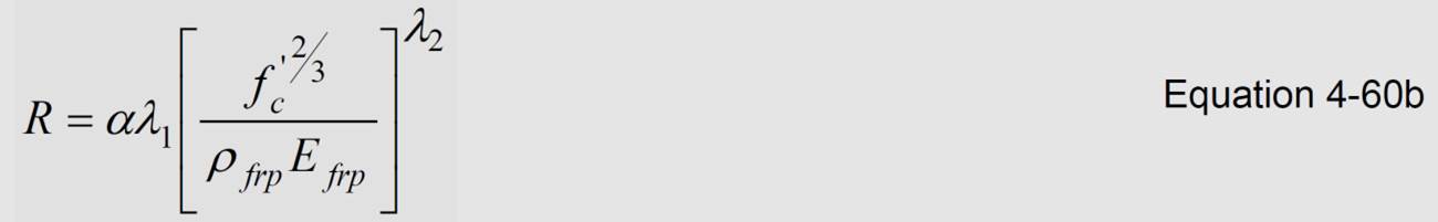

For GFRP rupture, Triantafillou and Antonopoulos (2000) did not prescribe values
for the coefficients λ1 and λ2 since there was insufficient experimental data.
However, it may be reasonable to use the λ1 and λ2 values for AFRP as being also
applicable to GFRP, given the present state of knowledge; see for example Section
4.6.6.1 of this manual.
گردآوری شده توسط شرکت مهندسین کهن کارآزما – طراح و مجری FRP